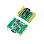
Interface Description 1 VM The power supply of the drive module is input according to the parameters of the motor and the measured range is 7 6 40V2 VCC Connect to 5V input do not input 3 3V otherwise it will affect the performance3 GND is the ground pinControl example when the above 3 pins are connected Task 1 A motor rotates forward duty cycle 50 Solution The two wires of motor A are connected to AOUT1 and AOUT2 respectively AIN1 is connected to low level and AIN2 is connected to 50 PWMOTask 2 B motor reverse duty cycle 20 Solution The two lines of motor B are connected to high level according to BOUTL BOUT2o BINI respectively and BIN2 is connected to 20 PWM If your PWM frequency is relatively high such as 10KHZ you need 2 PWM pins to control the forward and reverse rotation If you use Arduin s default frequency of 500Hz PWM You can use a 10 and a PWM pin to control the forward and reverse rotation But the effect is not as good as 2 PWM pins Parameters Function It can control the forward and reverse rotation of 2 motors for example the balance car onlyrequires one of this module Voltage 7 6 40VCurrent The module has current limit protection 2A overcurrent will not power off only limit the maximum output currentControl 4 PWM pins are required if inversion is not required only 2 PWM pins are required it is much simpler to use than 298Weight 3gSize 23 18 3MMLead out 2 rows of 7pin pin headersSpacing 20MMPackage includes 1 x Motor Dri
Price history
Sep 4, 2022
€4.41

