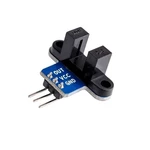
Wiring 1 5 5 is the positive input port of the power supply which can be connected to a voltage of 3 3V 5V2 GNDGND is the negative input port of the power supply3 OUTOUT is the signal output port which is connected to the I O port of the MCU generally connected to an external interruptNote Arduin0 should set the I O port of MCU to input mode receive mode otherwise it cannot be used For other MCUs or more advanced control boards such as Arm if you want to set the I O port to input output mode you must set it to input mode receive mode otherwise it cannot be used The 51 series MCU can be used directly without setting the input and output mode Programming The OUT port of the speed measurement module is connected to the external interrupt port of the MCU and it is an external buffer whenever an infrared ray is turned on Measuring distance The output of the speed sensor is a pulse signal and each pulse is interrupted once when the infrared ray is turned on it is a low level so we set the interrupt as a low level touch mode Generally there are integer grids on the code disc No matter how many grids there are the principle is the same For example a 10 grid code disc means that there are 10 blank grids After the motor rotates once the ray is turned on 10 times and the external low level touch method is 10 times After installing the above ideas our speed sensor can play an effect We know that there are 10 interruptions in one circle so we calculate the
Historique des prix
4 sept. 2022
2,64 €

